Model T speedometer
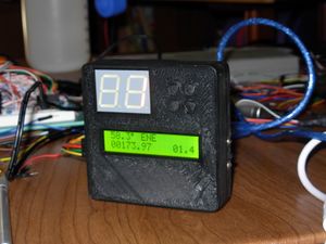
The Ford Model T never had a speedometer or odometer. This can make it more difficult to drive around in 2018 like a normal car. Therefore, using the same technology as my GPS box, I created a small device to perform this function. It has other uses as well.
Device Description
The device itself consists of an Arduino Pro mini clone (atmega328p microcontroller) as the main cpu/controller. A GY-NEO6MV2 GPS is used to provide location information to the processor, and I use the tinyGPS++ library to extract lat/long, speed, and direction from the GPS module. An 1602 LCD supplies the user interface. Since the LCD characters are too tiny to see from a distance while driving, a larger 2 digit 7 segment display is included, on which is displayed the speed in MPH. An 18650 battery and boost converter module supplies power, which can last many hours. Another module supplies protection circuitry and charging for the battery. All the small module boards are common and inexpensive from various Chinese distributors on eBay or Aliexpress.
To ensure that data is saved when the unit is turned off, I used a Microchip 47C16 EERAM, which is nothing more than an normal Static RAM (which loses its data on power off) that saves itself to a normal EEPROM when power is lost, and loads the data back into RAM on power up. A small capacitor supplies extra power to this chip when the power goes out. This device is critical, because the data needs to be stored often enough to ensure nothing gets lost when the device is suddenly switched off, but not so often that the nonvolatile storage (like EEPROM) would get worn out.
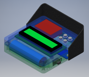
I designed a 3D printed clamshell case that would fit the entire device inside. I made cad models of all the components so I could ensure they would all fit together inside the same case. The case is designed with the LED on the left, so the driver could see it better. Four buttons on the right provide all the user interfacing to the device, and there is just enough space above the holder for the buttons to fit the tiny GPS antenna so that it is facing upwards through the top of the device. On the back, four self tapping screws hold the unit together, and several magnets hold the device onto the flat metal dash of the Model T. I found that painting the back of the device with some liquid electrical tape helps create a non-slip coating that prevents the device from sliding off the dash.
After the device was built, I found that the LED display was not very visible in direct sunlight, so I created a detachable sunshade that is also held onto the dash with magnets.
Operation
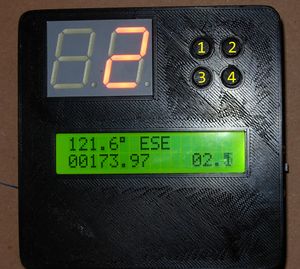
The main UI is organized as a series of many "screens" that can be shown on the 16x2 LCD. These screens can contain thing like distance or speed measurements, or a setting. The user interface is operated with 4 buttons, whose locations are shown in the image at right. In general, buttons 2 and 4 move between the different screens. Some screens contain editable fields, such as target latitude and longitude. For these editable screens, button 1 enters "edit" mode. While in edit mode, buttons 2 and 4 function as add/subtract buttons, and button 3 moves a cursor along the field. For some of the other editable screens, like the trip odometers, button 3 acts as a reset button to reset the field to zero, because manually editing the trip distance up or down is probably not what you wanted to do anyway. In either case, while in edit mode, pressing button 1 again will return the device to normal operation.
Units are in miles and miles per hour, (and degrees for compass bearings) since those are the units we use on our streets in the United States.
The full listing of the screens is listed below.
- #0 - "Main" screen showing a compass, the total odometer (all time running distance total), and a smaller version of the speedometer.
- #1 - Trip odometer 1 (resetable)
- #2 - Trip odometer 2 (resetable)
- #3 - Trip odometer 3 (resetable)
- #4 - Trip odometer 4 (resetable)
- #5 - Current position of the device; latitude on the top line, longitude on the bottom line.
- #6 - Time and Date (in UTC (or GPS time?))
- #7 - Altitude, in feet
- #8 - Speed, in miles per hour. Use this one if the 7 segments are not visible.
- #9 - Input latitude of waypoint.
- #10 - Input longitude of waypoint.
- #11 - Distance and angle to target waypoint defined by screens 9 and 10.
- #12 - Number of GPS satellites visible to the GPS receiver.
- #13 - GPS HDOP - this is a measure of "how good" the GPS fix is, the lower the better.
- #14 - Backlight - editable section that turns the LCD backlight on or off. Zero turns it off, anything else turns it on.
- #15 - Runtime - the number of seconds since the unit has been powered on.
- #16 - Total runtime - the total time that the unit has been powered on. This number is saved at power down and keeps going up as long as the unit is on.
- #17 - Battery voltage of the 18650 power source.
- #18 - 7 segment display setting. Value 0 keeps the display off, 1 turn it on, and 2 displays a leading zero also.
- #19 - Last Lat - Latitude of location that the device was last powered down.
- #20 - Last Lng - Longitude of location that the device was last powered down.
- #21 - Distance and angle to last departed location.
- #22 - Distance since powered on.
- #23 - High score - the fastest speed observed since power on.
Revisions
Summer 2019 - added:
- #22 - distance traveled since the unit was powered on
- #23 - High Score (max speed obtained since power on)
Files
Arduino source code is below. They do not include the needed libraries:
- LiquidCrystal_I2C
- NeoSWSerial
- TinyGPSPlus
- SerialRAM
File:Modelt-arduino-v3.1.zip - Version 3.1 File:Modeltspeed-Main-v3-2.zip - Current Arduino sketch (as of Aug 2018)


