2024-09-10 | [videos] [misc]
previous: HP 85A Tape Repair - next: Fish Singer
originally posted on hackaday.io
So you want a tiny game, eh? How small can it be? Any sane designer would tell you that your design can be as small as the chip package it comes in. This is not true! An IC is usually just one tiny square cut from a silicon wafer. Depending on the chip package used (and whether or not it has thermal properties you care about), most of a package is just stamped metal pieces, which are the leads of the component, and excess plastic, which can be milled away to make room for more components.
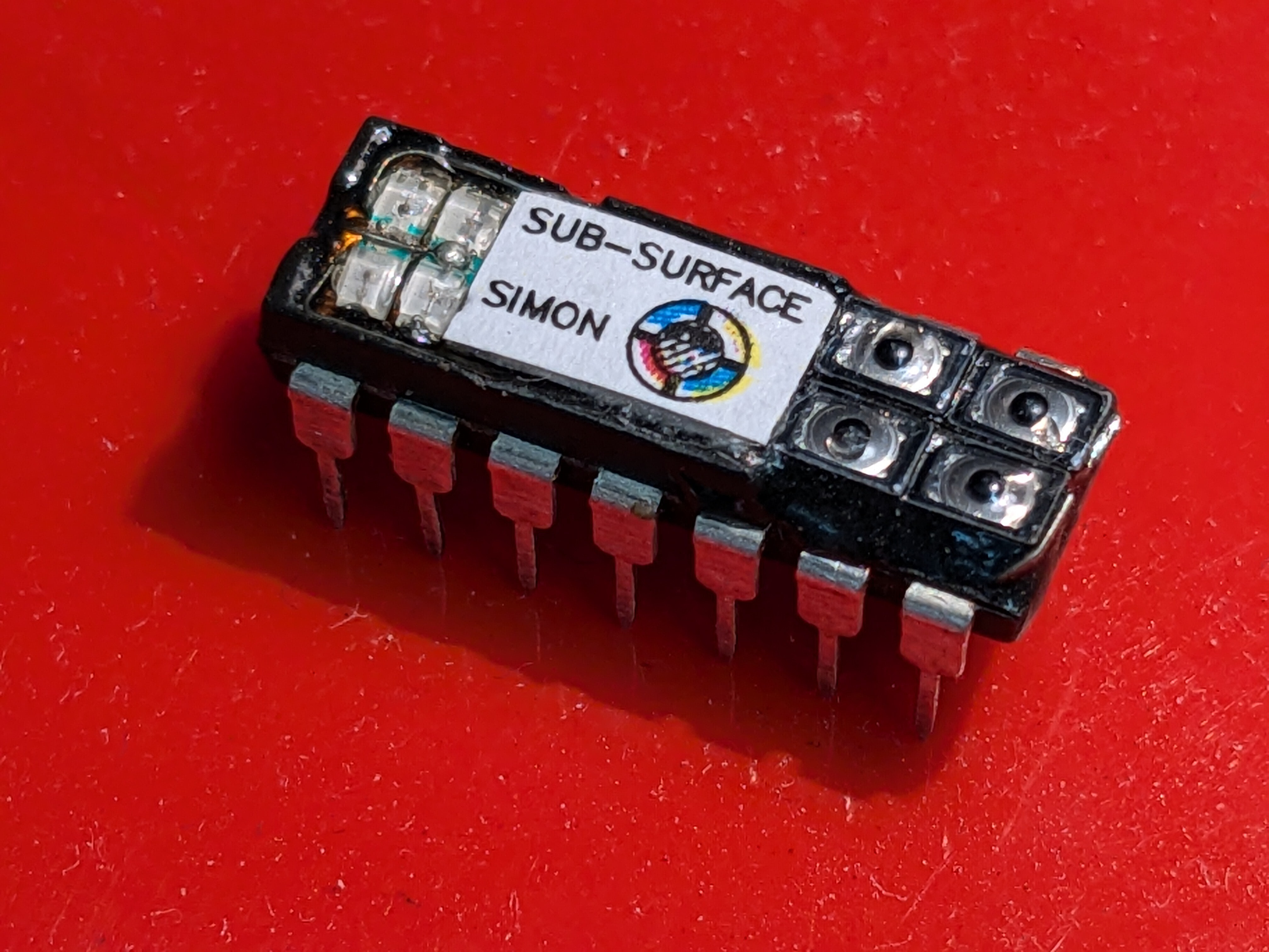
If surface mount is mounting components on the surface, then sub-surface mount is mounting them BELOW the surface.
Most of the time when people say "I fit a game into one chip" this is NOT what they mean.
Made for the Hackaday 2024 Tiny Games Contest and for my own amusement.
Someone left me a comment recently complaining that surface mount parts are too difficult to work with. I don't find this to be the case - most of my work has been done mostly in surface mount only for a few years. This has left we with a decent stock of larger DIP parts, and the opportunity for a challenge much more difficult than soldering the tinniest 0201 resistors.
Sure, it isn't the smallest possible game - you could somewhat easily make a PCB and use the same BOM here in even smaller SMD packages, but that's hardly the point now is it?
Here is a video of the assembly process. There is some gameplay footage around 6:10. I don't do anything special in order to solder this, just a fine iron tip, hot air gun, flush cutters, x-acto knife, and some tweezers. I also don't use any optics, though it may help that I'm slightly nearsighted. And also some flux jelly (that's the real secret weapon).
Chip is an AtTiny84A in a DIP-14 package, since it's what I had on hand. Programming is done using the Arduino IDE with [https://github.com/SpenceKonde/ATTinyCore]. I don't use the bare Arduino IDE very much anymore (platformIO + vscode is a much better experience), but I wanted something which was extremely quick to set up (and it was). I knew I wanted a few LEDs and some buttons, but I wasn't really sure what game to make. If I could fit 4 of each than I could do Simon. The original Simon used a TMS1000 microcontroller, so the attiny is surely overkill for processing power.
The hardware is just: 4 pins with an LED with resistor to GND and 4 more pins with a switch to GND. If you want sound, that's another pin with a resistor and speaker to GND. It doesn't get any easier than that.
Goals:
Milling was done with my CNC mill, but with the motors disconnected and manually turning the knobs. Milling cutter is one of those awful burr style super Amazon end mills (the kind with the fake painted on "coating"). They are cheap, but I only had a few on hand and so still did not want to break any more than I had to.
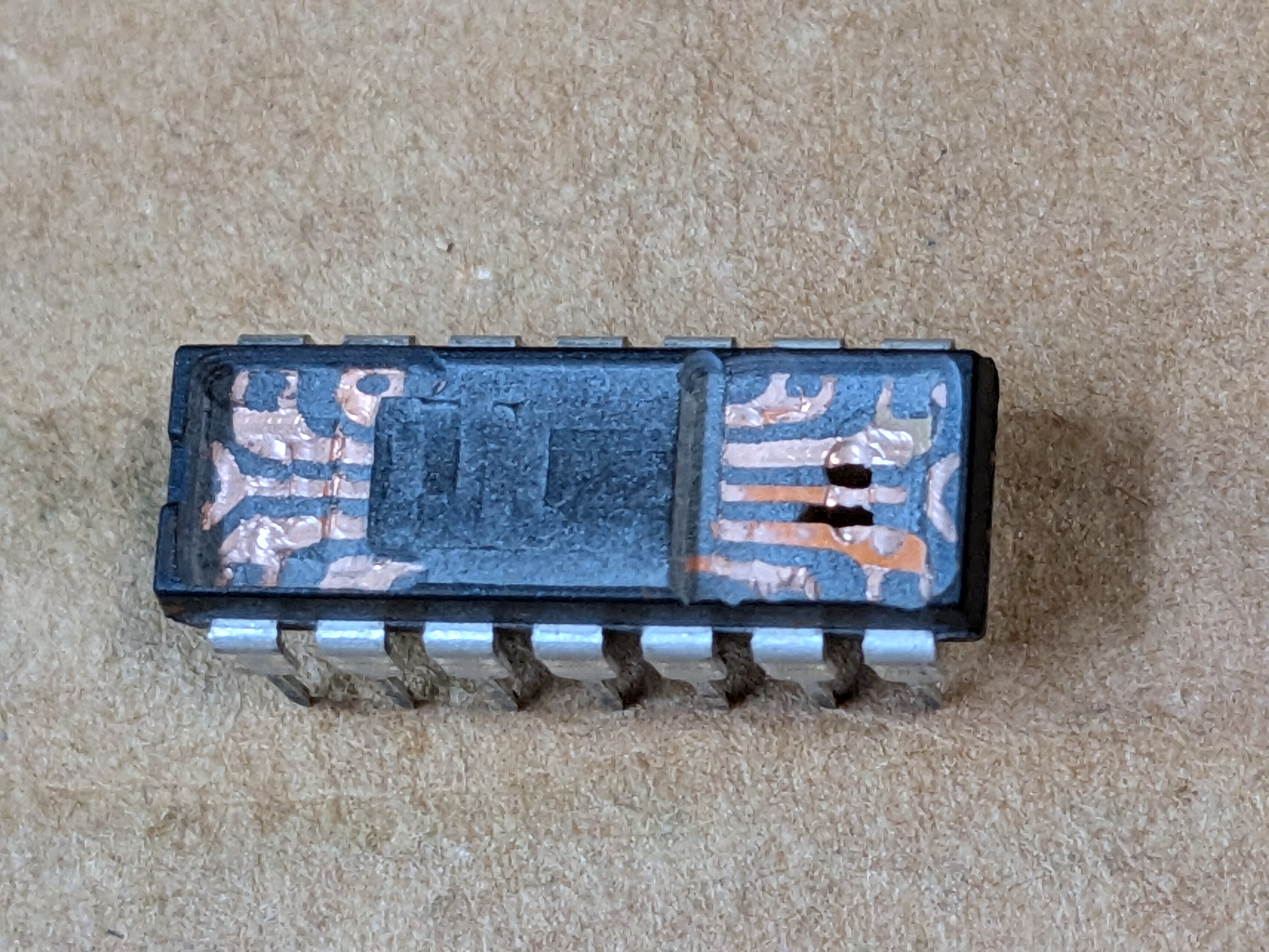
To the depth of the leadframe, everything is fair game except for around the die, and just beyond it where the bondwires are. It is all to easy to drive the mill too far and sever a bond wire, which are so small you'll never realize you hit one. I also discovered that the die was shifted to one end of the chip, and it was the end where I needed to access the 6 most inner pins, rather than just the 4 pins on each end. You also can't mill away everything - there still has to be enough material to hold the remains of the package together.
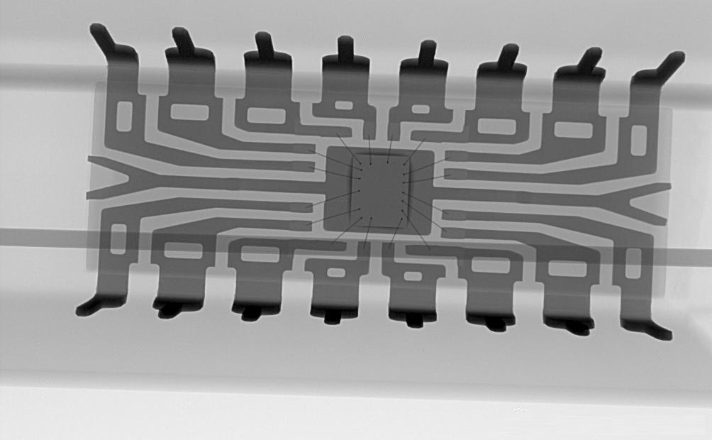
Here is an X-ray of a chip (image not mine; found it here). The tiny hair-like things are the bond wires. They are all that connect the chip to its pins. Consider how you would mill away the package in order to access those pins from the inside. You can actually do the same thing from the bottom of the chip (the bond wires are only on the top, and so you can mill across the whole surface), but that's a far less ideal location to put a user interface.
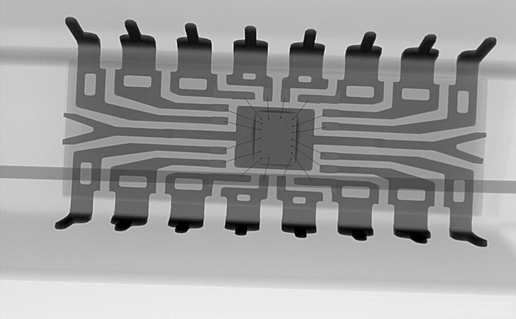
This naturally leads to a pocket at either end of the package, just big enough to hold a pinch of SMD components.
Between the careful monitoring of what I was doing, increased nervousness in trying not to break a bond wire or the bit, controlled breathing to blow away obscuring dust, and an awkward hunched over sitting position so I could reach the knobs, it made for a very uncomfortable milling experience!
To solder wires onto the exposed leadframe, I found the best technique was to apply some flux, then drop in a tiny slice of solder wire. Then, you heat the pins externally with a hot air gun. The heat will travel up the pin, and melt the solder. You cannot do it by simply aiming the hot air at the solder itself, because the rest of the pin's metal will carry the heat away. This is somewhat counterintuitive. The same technique can also be used to stop solder from melting when you don't want it to. Clamping those pins in the vice will carry away enough heat to stop the solder from melting.
The general technique I went for in assembly is to solder small wires to the leadframe with hot air, then build up the components separately (doing dead-bug SMD), and then dropping the assembled block of components into place, trimming and bending the wires over, then soldering them onto the needed places with a fine-tipped iron.
I tried to do the gluing steps last. Glue holds the components into place and adds structural integrity back to the package. But, solder flux stops the glue from sticking. So does rubbing alcohol which you would use to clean the flux (though mine is also water soluble). You can't solder without flux, but you can't keep the components in place without glue. So it is pretty tricky. I used hot glue for this first attempt. Hardened epoxy would be easier to carve back into the shape of a DIP package, but hot glue is what I had time for.
I left an extra pocket in the bottom of the chip since I wanted to fit a speaker inside there too, for sound. But, I didn't get to it in time. Do you know of any speaker which is 1/8" wide?