TRS-80 Plug 'n Power Controller
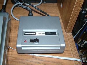
The original TRS-80 Plug 'n Power controller (catalog 26-1182)[1] was Radio Shack's 1981 answer to home automation. "Plug 'n Power" was actually the Radio Shack branding for products that speak the X10 protocol. If you're not familiar, X10 uses modules that send signals through the house AC lines to turn on and off lamps and appliances. They also made special wall switches and outlets so you could integrate X10 directly into the walls of your house, if you so choose. X10 devices are still made and sold, and the X10 system has been extended to control devices via IR, radio, and added sensors like motion detectors, cameras, and windows switches to make an entire security system.
However, we're only concerned with the original X10 power line system in this context. The TRS-80 plug n power system came with a small gray box that plugged into the cassette port and and AC outlet. With the included software, you could set up a schedule that would turn on and off your lights. The box even provides a real-time clock signal to run your schedule at the right time. You could also plug your tape recorder into the box, and by flipping the switch on the top, pass the signals through so you could either use the box or your tape recorder without having to unplug anything. The unit comes with two cassettes, containing a machine language "Home Control" program, for the model 1 and 3, and the color computer.
However, what my unit didn't come with is any kind of manual, even though it's in the original box. And neither do any of the other units that are available on eBay, which is where I got mine. As it turns out, I was very lucky to get the cassettes! There is next to no information on this piece of hardware anywhere online, besides the fact that it existed. That means no schematics, no software, and no programming information.
Naturally, the first thing I did was back up the content of those cassettes. There are instructions on the tape labels themselves that show how to load the tape with SYSTEM. To my relief, both the 16K and 32K versions of the program loaded just fine on my Model 1 without issue. I used the cmdfile utility under LDOS to back up the programs into CMD files. I also digitized the tapes using a tape recorder, although I am still unable to read them using any of the wav2cas program's I've found. Even so, I can always take a snapshot of ram with the programs loaded using the TRS80EI2, and you should expect a full backup soon.
The next part of the problem was trying to figure out how to use the software. The program it comes with has two modes, a direct control mode and one where you can set up a schedule. The direct control method was pretty simple to figure out, but the scheduling proved to use some weird unintuitive keyboard shortcuts. Lucky for me, I found an old article from Creative Computing [2], where, in 1982, somebody wrote a review of this unit, and helpfully included how to operate the software (thanks again to Jason Scott who has collected and uploaded thousands of old computer artifacts to the Internet Archive over the years).
But, there was still a nagging question. On the box, it said that there was a way to control the X10 modules from within a BASIC program. No doubt that this information would have been listed in the manual, which doesn't exist. The unit as it stands isn't that useful when you can only operate it with the existing program, I'd much rather be able to use it from within my own programs. The obvious way forward would be to reverse engineer the hardware and software.
Reverse Engineer
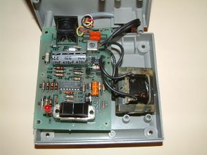
At first, I thought that the little grey box might get a command sent to it from the TRS-80 and then get sent out on its own time, but this idea was quickly abandoned when I opened the box and found only a small transformer and a PCB with just one quad op-amp chip. There were no smarts in here; obviously the TRS-80 must be doing all the work. I know that the box must be sending some kind of clock signal to the TRS-80, because the included control program came with an on-screen clock, which would not update unless the box was connected. The expansion interface also has a clock, but this accessory does not require it to work. The first step was to determine what kind of signal the box was creating for the TRS-80. I put a scope on what would be the tape out / trs80 in pins, and found that the box sends out a pulse about every 8 milliseconds. This is roughly 120Hz. The X10 protocol sends out little blips on the power line at the zero-crossings of the AC power, and that's really all there is to it; sometimes it sends out a 1ms blip of 120Khz at the zero crossing (what I will call a Mark), and other times there is nothing (a Space). This pulse signal must be the zero pulses; it looks like the trs-80 just sends out a pulse at the zero crossing when required.
The next step was to disassemble the included machine language program, which left me with a very confusing ASM file. It's easier to read than a hex file, but still very hard to read without any comments, especially because I am new to assembly (coming from higher level programming like C). However, I was able to find the section of code that interacts with the grey box. The standard TRS-80 uses only one of the 256 z80 ports (it memory maps everything else), and that port is at 0xff for the cassette. So, by searching the disassembly for any IN or OUT opcodes, I quickly found the sections that deal with the box interface, specifically, the section that would wait for a zero-crossing and send out a Mark. I found the section for Space too, but I couldn't get the code to work in my assembler programs, so I duplicated the Mark code and changed it so that it wouldn't actually send out anything, but would still stop anything else from happening until that zero crossing was received. While looking around the Mark code, I also found a section that would check the TRS-80 ROM to see if it was a model I or model 3. The model 3 has a faster system clock, so the program would need to be slowed down or the Mark would be sent out at the wrong time. Since I only have a Model 1, I omitted this from my assembly program.
With these fundamentals established, I can build up the rest of the building blocks of the X10 protocol. There's plenty of information online[3] on the details of X10. For a basic explanation, each X10 messages starts with three Marks and a Space. Then, 9 bits are sent, which contain the House code and either a Unit number, which selects that unit for further communication, or a Command, which makes the unit turn off or on. For the encoding of these bits, a value of 0 is sent as a space followed by a mark, whereas a value of 1 is sent as a mark followed by a space. For redundancy, each x10 message is sent twice, and there is a 6 zero-crossings minimum between one message and the next. That's about it, I just needed to build up the program into one easy to use CALL. Which leaves me with the following demo program:
Assembler Demo Program
org 5200h ;can be moved anywhere in RAM

test:
	call 3000h ;not needed unless you need to use trs80ei2 special loader functions while running this programe

	ld c,00000010b  ;select home code C (4 lower bits form House code - 0010 in this case)
	ld b,00011100b  ;select device 2 (5 lower bits - 11100)
	call x10msg
	ld b,00000101b  ;turn on device (instead of device code, use a Command code - 00101 makes previously selected device turn on)
	call x10msg

	call jwait ;(this is just a placeholder function that pauses the program for a couple seconds; not needed in regular usage)

	ld c,00000010b  ;select device C2
	ld b,00011100b
	call x10msg
	ld b,00000111b  ;turn off device (00111)
	call x10msg

	call jwait

jp test

jwait:
	push bc
	push de
	ld d,002h
	ld c,0ffh
	ld b,0ffh
	loop8:
	loop7:
	loop6:
		nop
		djnz loop6
	dec c
	jr nz,loop7
	dec d
	jr nz,loop8
	pop de
	pop bc
	ret

x10msg: ;send an x10 message - set C to House Code and B to Control/Device Code
	push de
	push af
	ld a,b
	ld d,2
	loop14: ;do the whole thing twice (x10 protocol standard)
	call x10start ;send out x10 start code
	ld e,c
	ld b,4
	rl e ;get to the data from the left
	rl e
	rl e
	rl e
	loop12: ;send out the house code (4 bits)
		rl e
		call nc,x10bit0
	    call c,x10bit1
		djnz loop12
	ld e,a
	ld b,5
	rl e
	rl e
	rl e
	loop13:  ;send out the device/control code (5 bits)
		rl e
		call nc,x10bit0
	    call c,x10bit1
		djnz loop13
	dec d
	jr nz, loop14 ;end loop14
	call x10wait
	pop af
	pop de
	ret

x10start:
	call pulsem
	call pulsem
	call pulsem
	call pulses
	ret
x10bit0: ;sends an x10 bit with value 0 (mark followed by space)
	call pulses
	call pulsem
	ret
x10bit1: ;sends an x10 bit with value 1 (mark followed by space)
	call pulsem
	call pulses
	ret
x10wait: ;waits six cycles between x10 transmissions
	push bc
	ld b,06h
	loop5:
		call pulses
		djnz loop5
	pop bc
	ret

pulsem: ;pulse - sends Mark
    push bc
    push af
	LD	C,02H
	waitinpA:
		IN A,(0FFH)
		rla
		jr nc,waitinpA
	casouthlA:
	ld a,01h
	out (0ffh),a
	LD	B,87H
	loop1A:
		djnz loop1A
	LD	A,02H
	out (0ffh),a
	LD	B,0F0H
	loop2A:
		djnz loop2A
	dec c
	jr nz,casouthlA
	ld a,01h
	out (0ffh),a
	ld b,87h
	loop3A:
		djnz loop3A
	ld a,02h
	OUT	(0FFH),A
	pop af
	pop bc
	ret

pulses: ;pulse - sends Space
    push bc
    push af
	LD	C,02H
	waitinpB:
		IN A,(0FFH)
		rla
		jr nc,waitinpB
	casouthlB:
	ld a,02h
	out (0ffh),a
	LD	B,87H
	loop1B:
		djnz loop1B
	LD	A,02H
	out (0ffh),a
	LD	B,0F0H
	loop2B:
		djnz loop2B
	dec c
	jr nz,casouthlB
	ld a,02h
	out (0ffh),a
	ld b,87h
	loop3B:
		djnz loop3B
	ld a,02h
	OUT	(0FFH),A
	pop af
	pop bc
	ret
Files
I have recorded the 2 software tapes that came with this unit. There is software for Model I level1, level2 16K and 32K, Model III, and CoCo. File:Trs80-plugnpower-tapes.zip
Or on Internet Archive: [[1]]


