COW arm: Difference between revisions
| (7 intermediate revisions by the same user not shown) | |||
| Line 11: | Line 11: | ||
At present, the arm design looks more like a crane or backhoe than an arm. | At present, the arm design looks more like a crane or backhoe than an arm. | ||
==Encoders== | ==Encoders== | ||
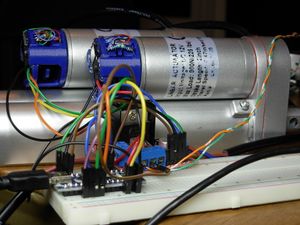
Yes, I made my own | [[File:Cow-encoders-test-v1.jpg|thumb|Linear actuators with the encoders installed, on a breadboard for testing.]] | ||
Yes, I made my own encoders for this project just like the ones I used on my wheelchair wheels. This is probably a bad idea and you should probably use of the shelf encoders. But, I don't want to wait for parts to arrive and I don't want to make any special adapters, and I again want to see if I can, so there you go. | |||
===Preparing the arm/forearm motors=== | ===Preparing the arm/forearm motors=== | ||
| Line 40: | Line 40: | ||
q2 = atan(y/x) + atan((a2*sin(-q1-pi))/(a1+a2*cos(-q1-pi))); | q2 = atan(y/x) + atan((a2*sin(-q1-pi))/(a1+a2*cos(-q1-pi))); | ||
</pre> | </pre> | ||
The last step in this is to tell us how we need to extend our actuators to get the angles we just found, which is found from the law of cosines: | The last step in this is to tell us how we need to extend our actuators to get the angles we just found, which is found from the law of cosines: | ||
</pre> | </pre> | ||
act2 = sqrt(l2^2+m2^2-2*l2*m2*cos(q1)); | |||
act1 = sqrt(l1^2+m1^2-2*l1*m1*cos(ng2*(pi/180)-q2)); | |||
</pre> | </pre> | ||
where: | |||
* q1 is the angle (radians) between the forearm and arm (at the top) | |||
* q2 is the angle (radians) between the arm and the horizon | |||
* x and y are Cartesian coordinates for where you want the end of the arm, with the origin at the arm shoulder | |||
* a1 and a2 are the lengths of the arm and forearm, respectively | |||
* m1 and l1 are the distances to the arm actuator mount points, measured from the shoulder bearing | |||
* m2 and l2 are the distances to the forearm actuator mount points, measured from the elbow bearing | |||
* ng2 is the angle (degrees) from the horizon to the line between the shoulder and lower actuator mount point | |||
That's pretty much it. We can just feed those actuator lengths into the controller for our actuator and the arm will position itself to the point that we want. However, this won't necessarily be a straight line move, because the actuators will just go at their own speeds. To fix this, I broke up the move into a bunch of tiny segments, and we command the arm to move to the endpoints of each segment, in sequence. To do this properly, we might first want to know the initial position of the arm. I use forwards kinematics for this, by recalculating the angles given the position of the arm actuators, and then the position of the end of the arm. | That's pretty much it. We can just feed those actuator lengths into the controller for our actuator and the arm will position itself to the point that we want. However, this won't necessarily be a straight line move, because the actuators will just go at their own speeds. To fix this, I broke up the move into a bunch of tiny segments, and we command the arm to move to the endpoints of each segment, in sequence. To do this properly, we might first want to know the initial position of the arm. I use forwards kinematics for this, by recalculating the angles given the position of the arm actuators, and then the position of the end of the arm. | ||
<pre> | <pre> | ||
q1c=acos((m2^2+l2^2-act2^2)/(2*m2*l2)); | |||
q2c=-acos((m1^2+l1^2-act1^2)/(2*m1*l1))+ng2*(pi/180); | |||
x2= | x2=a2*cos(pi-q1c-q2c)+a1*cos(q2c) | ||
y2= | y2=a2*sin(pi+q1c+q2c)+a1*sin(q2c) | ||
</pre> | </pre> | ||
'''x2''' and '''y2''' are the position of the end of the arm. The idea is that we get the arm position from the actual reporting of the encoders, and therefore have a better idea of where the arm is, rather than assume it's in the spot we commanded it to go last time, in case I do ever want to control the arm manually. | '''x2''' and '''y2''' are the position of the end of the arm. The idea is that we get the arm position from the actual reporting of the encoders, and therefore have a better idea of where the arm is, rather than assume it's in the spot we commanded it to go last time, in case I do ever want to control the arm manually. | ||
''20190819 - The above formulas have been fixed. In my original version, I mixed up which arm was link 1 and link 2, but it still seemed to work. Now that I want to use links of different lengths, I've had to fix it.'' | |||
===The Real Math=== | |||
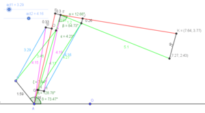
[[File:Cow-real-arm-geogebra-v1.png|thumb|The geometry of the real arm looks much more complicated. The ideal arm is still there (the green lines), but I have added all the off-axis mounts and hinges that form the real arm.]] | |||
Once I got the above equations all into Arduino code and attached up the actuators back on the arm, I attached a pen to the end of the arm and tried to draw a square, going in straight lines. It came out lopsided, and lines that were supposed to be straight were curved. Why? | |||
Well, the math we just did above assumes all the pins, bearings, etc are along the centerlines of the two arm segments. In the arm we just built, this is not the case, as we used brackets that bring these pins away from the centerlines. This means that the end of the arm we calculate for and the real arm are two different things. However, they are both rigid bodies, so in theory we should be able to add angle and/or distance offsets and correct for these off-axis hinges. To do this, I'm going to go back to GeoGebra and make a model accurate to the real arm, then pick the adjusted (projected?) measurements off to use in my kinematics. | |||
The steps for the kinematics are really not all that different. First, we calculate the angles. The forearm is always a constant angle away from the ideal forearm, so we can just add on that angle. In calculating the actuator lengths, we take care of the off-axis actuator mounts by adding more correction angles (the purple lines in the image above, which is always a constant length and a constant angle away from the ideal arm links). | |||
The revised arm equations are below: | |||
First, the constants: | |||
<pre> | |||
pi=3.1415926; | |||
a2 = 630; %len forearm | |||
m2 = 421; %len from pivot to actuator | |||
l2 = 120; %len from pivot to actuator | |||
a1 = 498; %len arm | |||
m1 = 411; | |||
l1 = 159; | |||
%correction factors (ideal to real) | |||
ofa2 = -12.66*(pi/180); %correction angle for forearm (ideal to real add) | |||
ofma2 = 4.23*(pi/180); %angle between ideal arm and elbow-m2 line | |||
ofml2 = 419; %length of elbow-m2 line | |||
ofma1 = 7.94*(pi/180); %angle between ideal arm and shoulder-m1 line | |||
ofml1 = 415; %length of shoulder-m1 line | |||
ng2 = 128.78*(pi/180); %offset angle betweem horz and lever arm2 | |||
</pre> | |||
Inverse kinematics: | |||
<pre> | |||
%find the angles | |||
q1 = pi-acos((x^2+y^2-a1^2-a2^2)/(2*a1*a2)); | |||
q2 = atan(y/x) + atan((a2*sin(-q1-pi))/(a1+a2*cos(-q1-pi))); | |||
q1d=q1*(180/pi) | |||
q1 = q1 + ofa2; %the real forearm is slightly above the ideal one | |||
q2d=q2*(180/pi) | |||
q1d=q1*(180/pi) | |||
%angles to actuator lengths (using law of cosines) | |||
act2 = sqrt(l2^2+ofml2^2-2*l2*ofml2*cos(q1-ofma2)); | |||
act1 = sqrt(l1^2+ofml1^2-2*l1*ofml1*cos(ng2-q2-ofma1)); | |||
out=[act1,act2]; | |||
</pre> | |||
Forward kinematics: | |||
<pre> | |||
%back to x and y, using actuator positions (fwd kinematics) | |||
q2c=acos((ofml2^2+l2^2-act2^2)/(2*ofml2*l2))+ofma2-ofa2; | |||
q1c=-acos((ofml1^2+l1^2-act1^2)/(2*ofml1*l1))+ng2-ofma1; | |||
q1cb=q1c*(180/pi) | |||
q2cb=q2c*(180/pi) | |||
x2=a2*cos(pi-q2c-q1c)+a1*cos(q1c) | |||
y2=a2*sin(pi+q2c+q1c)+a1*sin(q1c) | |||
</pre> | |||
==Files== | |||
* GeoGebra files for the ideal arm: [[File:Cow-arm-lower-upper-v3-ggb.zip]] | |||
* GeoGebra files for the real arm: [[File:cow-v6-arm-full.zip]] | |||
Latest revision as of 10:04, 22 August 2019
For this year's Winter Camp, Space is the theme. Therefore, after upgrading my electric wheelchair robot base this spring with a new motor controller, I decided that it should also have a robotic arm, making it useful as a Mars rover - esque robot platform. The wheelchair base weights a hefty 100+ pounds, and I want this arm to be actually useful (ie, able to lift more than a tissue box). I have named it the Cow arm, as it is designed to be beefier than those crummy kit arms that use servos (Ok, well, it has to be called something).
Upper and Lower Arm
I designed this arm after seeing this Hackaday.io project which uses linear actuators to provide forces along the length of the arm, much like the muscles in our own arm. Many arm designs I have seen use very high torque gearmotors in the arm joints to provide torque on the arm, but I don't have the ability to make one and they are astronomically expensive. Meanwhile, these linear actuators cost just 10s of dollars. I picked up a couple for testing, and if they work, they should take care of the largest force sections of the arm straight away.

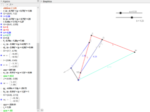
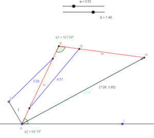
I also began to design the geometry of the arm; for this I have used a free program called GeoGebra, which I had remembered from a class I took. This program is essentially the electronic version of a paper, compass and straightedge. More importantly, objects can be changed - for example, I can change the diameter of a circle - and the rest of the lines will instantly update themselves to the new position. I can even attach the size of a circle to a slider, and drag it around to see what changing the size does in real time. It doesn't have all the constraint features of a CAD package, but the dynamic updating ability is really powerful.
I constructed the basic arm design I wanted to use, and then adjusted the joints of the linear actuators of the arm around until I got the range of the arm about how I wanted. Also, GeoGebra supports vectors, so by using the maximum force listed by the linear actuators and some vector projection, I could estimate the max force I might expect to pick up at the end of the arm. Obviously, this varies depending on how far the arm is extended, just like our own arms. Neglecting the weight of the arm itself, I was quite impressed to realize the arm might be able to pick up 10-30 pounds quite easily.
At present, the arm design looks more like a crane or backhoe than an arm.
Encoders
Yes, I made my own encoders for this project just like the ones I used on my wheelchair wheels. This is probably a bad idea and you should probably use of the shelf encoders. But, I don't want to wait for parts to arrive and I don't want to make any special adapters, and I again want to see if I can, so there you go.
Preparing the arm/forearm motors
Part of this project needs me to know how far the linear actuators are extended. There's no good way to attach an encoder to the linear actuators as is, you would probably have to use a big external linear displacement sensor, which sounds expensive. If I could just put a rotary encoder on the motor, I could figure out the displacement that way. It doesn't even have to be that high precision, because the gearing turns our few pulses into a few hundred over the span of the linear actuator.
I decided to do this by extending the motor shaft out the back of the motor. To do this, I started with a section of 1/8 inch drill rod, which is the same size as the original shaft. The drill rod also has a pretty good outside diameter tolerance. Next, I replicate the features of the original shaft. At the end is a D shaped key on which the drive gear attaches; this was milled on the horizontal mill. Next, the middle of the shaft is knurled slightly, to make sure the motor armature has a nice press fit onto it. I then leave the rest of the new shaft as long as I want it to stick out the back of the motor.
Now comes the tricky part. Very carefully, tap out the existing shaft from the armature. This is a press fit, but some of the armature pieces are made from easily squished plastic. Also, the commutator is not keyed to the armature by anything other than the shaft, so be very careful not to rotate it once the existing shaft is out. With the same care, the new long shaft can be tapped in.
The last modification is in the motor end bell. Using a small drill, I put my drill through the rear bearing and carefully drilled through the cover. Then, the end bell can be flipped over and a larger than 1/8 drill used to enlarge the hole so the longer shaft can pass freely out of it. Be sure not to drill into the bearing when doing this, and clean out all the shavings afterwards.
Add some oil to the bearings, and the modified motor can now be put back together. "But wait," I can hear you say, "Doesn't this mess up all the motor balances and such?" Well, yeah, technically. But these motors are not super precise to begin with, and I really haven't noticed much in the way of any extra vibration.
So now the motors can be reinstalled in the linear actuator, but have the added benefit of an accessible shaft.
Software/The Math
There's one big difference between the arm I just designed and the one attached onto my shoulder - how do you control it? When we want to pick something up, we don't think about how our muscles need to move, we just move our arm towards the object. With this arm, ideally I don't want to manually control it by moving each actuator. I should be able to just specify a location, and the arm should go there.
We can do this with a concept called inverse kinematics. Inverse kinematics can tell us the angles of the arm joints that we need to get to any given points. This is a much harder process than forward kinematics, which is what we do if we have the angles of the arm and want to see where it will end up. Inverse kinematics can involve a lot of fancy and complicated math, with linear algebra and matrices involved, but for a simpler arm like mine, we can just use concepts from geometry and trig functions. Actually, we don't even need to do that, because a 2 link arm like mine is usually the first or second example in the book if you happen to search up "inverse kinematics" on Google. The derivation comes from law of sines and cosines, but at the end of the day we end up with the following formulas:
q1 = pi-acos((x^2+y^2-a1^2-a2^2)/(2*a1*a2));
q2 = atan(y/x) + atan((a2*sin(-q1-pi))/(a1+a2*cos(-q1-pi)));
The last step in this is to tell us how we need to extend our actuators to get the angles we just found, which is found from the law of cosines:
act2 = sqrt(l2^2+m2^2-2*l2*m2*cos(q1)); act1 = sqrt(l1^2+m1^2-2*l1*m1*cos(ng2*(pi/180)-q2));
where:
- q1 is the angle (radians) between the forearm and arm (at the top)
- q2 is the angle (radians) between the arm and the horizon
- x and y are Cartesian coordinates for where you want the end of the arm, with the origin at the arm shoulder
- a1 and a2 are the lengths of the arm and forearm, respectively
- m1 and l1 are the distances to the arm actuator mount points, measured from the shoulder bearing
- m2 and l2 are the distances to the forearm actuator mount points, measured from the elbow bearing
- ng2 is the angle (degrees) from the horizon to the line between the shoulder and lower actuator mount point
That's pretty much it. We can just feed those actuator lengths into the controller for our actuator and the arm will position itself to the point that we want. However, this won't necessarily be a straight line move, because the actuators will just go at their own speeds. To fix this, I broke up the move into a bunch of tiny segments, and we command the arm to move to the endpoints of each segment, in sequence. To do this properly, we might first want to know the initial position of the arm. I use forwards kinematics for this, by recalculating the angles given the position of the arm actuators, and then the position of the end of the arm.
q1c=acos((m2^2+l2^2-act2^2)/(2*m2*l2));
q2c=-acos((m1^2+l1^2-act1^2)/(2*m1*l1))+ng2*(pi/180);
x2=a2*cos(pi-q1c-q2c)+a1*cos(q2c)
y2=a2*sin(pi+q1c+q2c)+a1*sin(q2c)
x2 and y2 are the position of the end of the arm. The idea is that we get the arm position from the actual reporting of the encoders, and therefore have a better idea of where the arm is, rather than assume it's in the spot we commanded it to go last time, in case I do ever want to control the arm manually.
20190819 - The above formulas have been fixed. In my original version, I mixed up which arm was link 1 and link 2, but it still seemed to work. Now that I want to use links of different lengths, I've had to fix it.
The Real Math
Once I got the above equations all into Arduino code and attached up the actuators back on the arm, I attached a pen to the end of the arm and tried to draw a square, going in straight lines. It came out lopsided, and lines that were supposed to be straight were curved. Why?
Well, the math we just did above assumes all the pins, bearings, etc are along the centerlines of the two arm segments. In the arm we just built, this is not the case, as we used brackets that bring these pins away from the centerlines. This means that the end of the arm we calculate for and the real arm are two different things. However, they are both rigid bodies, so in theory we should be able to add angle and/or distance offsets and correct for these off-axis hinges. To do this, I'm going to go back to GeoGebra and make a model accurate to the real arm, then pick the adjusted (projected?) measurements off to use in my kinematics.
The steps for the kinematics are really not all that different. First, we calculate the angles. The forearm is always a constant angle away from the ideal forearm, so we can just add on that angle. In calculating the actuator lengths, we take care of the off-axis actuator mounts by adding more correction angles (the purple lines in the image above, which is always a constant length and a constant angle away from the ideal arm links).
The revised arm equations are below:
First, the constants:
pi=3.1415926;

a2 = 630; %len forearm
m2 = 421; %len from pivot to actuator
l2 = 120; %len from pivot to actuator

a1 = 498; %len arm
m1 = 411;
l1 = 159;

%correction factors (ideal to real)
ofa2 = -12.66*(pi/180); %correction angle for forearm (ideal to real add)
ofma2 = 4.23*(pi/180); %angle between ideal arm and elbow-m2 line
ofml2 = 419; %length of elbow-m2 line
ofma1 = 7.94*(pi/180); %angle between ideal arm and shoulder-m1 line
ofml1 = 415; %length of shoulder-m1 line
ng2 = 128.78*(pi/180); %offset angle betweem horz and lever arm2
Inverse kinematics:
%find the angles
q1 = pi-acos((x^2+y^2-a1^2-a2^2)/(2*a1*a2));
q2 = atan(y/x) + atan((a2*sin(-q1-pi))/(a1+a2*cos(-q1-pi)));
q1d=q1*(180/pi)
q1 = q1 + ofa2; %the real forearm is slightly above the ideal one
q2d=q2*(180/pi)
q1d=q1*(180/pi)

%angles to actuator lengths (using law of cosines)
act2 = sqrt(l2^2+ofml2^2-2*l2*ofml2*cos(q1-ofma2));
act1 = sqrt(l1^2+ofml1^2-2*l1*ofml1*cos(ng2-q2-ofma1));
out=[act1,act2];
Forward kinematics:
%back to x and y, using actuator positions (fwd kinematics)
q2c=acos((ofml2^2+l2^2-act2^2)/(2*ofml2*l2))+ofma2-ofa2;
q1c=-acos((ofml1^2+l1^2-act1^2)/(2*ofml1*l1))+ng2-ofma1;
q1cb=q1c*(180/pi)
q2cb=q2c*(180/pi)
x2=a2*cos(pi-q2c-q1c)+a1*cos(q1c)
y2=a2*sin(pi+q2c+q1c)+a1*sin(q1c)
Files
- GeoGebra files for the ideal arm: File:Cow-arm-lower-upper-v3-ggb.zip
- GeoGebra files for the real arm: File:Cow-v6-arm-full.zip


