RC Wheelchair 2: Difference between revisions
| (17 intermediate revisions by the same user not shown) | |||
| Line 1: | Line 1: | ||
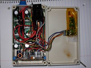
After my attempts to modify the settings of the existing wheelchair controller I accidentally | [[File:Wchmc2-v3-hbridge.jpg|thumb|The current (Aug 2019) incarnation of the project, showing the inside of the H-bridge module (the main electronics that ride on the robot platform). Messy, but does work quite well. From left, the H bridge PCB, main power relay, and LoRa radio module, with the Atmega1284 controller board at the bottom. The brown stain visible inside the lid is magic smoke residue from a wiring error :).]] | ||
After my attempts to modify the settings of the existing wheelchair controller I accidentally erased all the board settings and was left with an inoperable board. Since it is almost impossible to locate the correct file for my particular controller, I decided to construct a new motor controller. This would give me the added advantage of full control over each wheel motor, and I could write all my own control algorithms (though these do not necessarily come easily). I eventually extended this to support rotary encoders on each wheel, a custom radio control setup, and a robotic arm, turning an old electric wheelchair into a powerful general robot platform. | |||
This project is ongoing, and as it stands today, was completed over a series of many months, and I didn't document most of it at the time. The following is, in general, the process I went through to develop this system. | |||
==1 - DC motor controller (H-bridge)== | ==1 - DC motor controller (H-bridge)== | ||
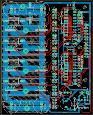
[[File:Wchmotor2-board.PNG|thumb|Board layout for the dual H-bridge controller ]] | |||
Like the original wheelchair, I needed to operate two 24V DC motors. I was not sure of the amperage, but I know that the batteries have an inline fuse for 12A, and that the original controller operates with just 4 single TO-220 mosfets on each motor (part numbers indicated rated for 30A). I couldn't test the motors under load very easily without a controller, so I estimated that a motor controller of 20-30A would do the job. | Like the original wheelchair, I needed to operate two 24V DC motors. I was not sure of the amperage, but I know that the batteries have an inline fuse for 12A, and that the original controller operates with just 4 single TO-220 mosfets on each motor (part numbers indicated rated for 30A). I couldn't test the motors under load very easily without a controller, so I estimated that a motor controller of 20-30A would do the job. | ||
I bought a cheap Chinese h-bridge board but it failed almost instantly, so for my next attempt I decided to roll my own. I based my design on the [http://www.robotpower.com/products/osmc_info.html open source Robot Power OSMC], with some changes. Firstly, I reduced the number of power mosfets by 1/4, since the original OSMC is rated for 160A, and I didn't need anywhere near that much power. So, instead of 4 mosfets on each branch, there is just one. The rest of the controller remains the same, which mostly consists of the HIP4081A mosfet controller. Next, I doubled up the controller, adding a second channel so I could drive a second motor. | The style of motor controller, in both the original wheelchair controller and my replacement is known as an H-bridge. In simple terms, it is a circuit using four switches, which allow you to connect and disconnect either terminal of a DC motor to either + or - of a battery. In this way, you can make the motor run in either direction, and even control the speed by turning on and off the switches really fast. | ||
I bought a cheap Chinese h-bridge board but it failed almost instantly, so for my next attempt I decided to roll my own. I based my design on the [http://www.robotpower.com/products/osmc_info.html open source Robot Power OSMC], with some changes. Firstly, I reduced the number of power mosfets by 1/4, since the original OSMC is rated for 160A, and I didn't need anywhere near that much power. So, instead of 4 mosfets on each branch, there is just one. The rest of the controller remains the same, which mostly consists of the HIP4081A mosfet controller. Next, I doubled up the controller, adding a second channel so I could drive a second motor. The last step was designing a PCB, which was straightforward except for the traces which would carry the high motor current. Since I wanted to use a cheap PCB service with correspondingly thin traces, I left off the solder mask on those parts (exposing the bare trace), and then filling the entire trace with excess solder, which has proved to work fine. | |||
The resulting board works fine, although there could be some improvements to improve the board layout (this is only the second board I have designed, ever). Additionally, the board lacks seperation for the logic power and motor power, forcing me to add it in later when I realized I still needed the board powered even when I wasn't using the motors. | |||
==2 - DC motor controller (Supporting components and processor)== | |||
More than 2 H-bridges are needed to operate the wheelchair. Each motor has an electromagnetic brake, so to be able to run the motors you must first apply power to the brake which will disengage it. I solved this by using a relay to apply power to the brakes. In addition, the same relay allows power to flow into the H-bridge. Therefore, no power can get to the motors with the brake on. This also serves as a safety feature of sorts, de-energizing high power parts of the circuit when they are not being used. Another, smaller mosfet allows a microcontroller to switch the relay. | |||
For the microcontroller, I used an ATMEGA1284P with the Mightycore arduino compatible firmware. This particular chip has plenty of IO pins, and enough PWM pins that aren't also using timers used by other functions of the chip. This makes it much easier to, say, change the PWM frequency and see how the motors perform, maybe even eliminating the PWM noise the motors make (though I haven't tried that yet). | |||
Basic functions of the microcontroller are: | |||
* turns on the relay (disables brakes and applies power) when motion is requested, and turns it off after a timeout when no motion is requested | |||
* provides PWM signals to the H-bridge (allows control of power to the motor from 0 to 100%) | |||
* calculates on the control algorithm (in first version, just a feedforward that adjusts power to each motor, in second version, this plus a PID controller that acts on measured motor speed) | |||
* derives wheel speed using two quadrature encoders | |||
* manages nrf24l01 radio for communication to remote control | |||
All that is left is a handful of power supplies to operate the radio and microcontroller, and some programming. | |||
==3 - Quadrature encoders== | |||
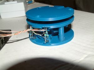
[[File:Wch2-encoder.jpg|thumb|A poorly hot-glued together encoder used for testing. The entire optical encoder consists of 15 components: 2 housing pieces, 1 rotor, 4 diode holders, 4 resistors, 2 IR leds, and 2 IR photodiodes. ]] | |||
The original version of this homemade controller just controlled the power to each wheel, but after I took a controls class in college, I thought it might be interesting to experiment with some closed loop controllers. This meant I would need feedback of the motors speed and/or position. I decided to make 3D printed encoders, and attach them to the ends of the motors, before the gearbox. These aren't the highest precision or most accurate, but they were easy and cheap to make. | |||
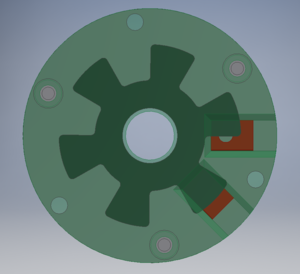
[[File:Wh2-encoder-asm.png|thumb|Cad assembly of the encoder, showing how the placement of the sensors (holes in red blocks) creates a 90 degree phase offset.]] | |||
First, I hooked up two pairs of IR leds and matching photodiodes. Then, I designed a rotor and housing to attach to the motor axle and the back housing of the motor. One interesting thing I learned when making these is that the ABS plastic I was using is somewhat transparent to IR light, but the parts were thick enough for this to not matter so much. The pairs of sensors are placed 90 degrees out of phase of each other, ie, when one sensor is in the center of a rotor vane, the other is at the edge of the rotor vane. When the rotor rotates and we observe the signals coming off of the sensors, we can figure out the direction and speed of the motor. Imagine drumming your fingers on a table; you can easily tell if the motion is left to right or right to left, as well as how fast you are doing it - this is the mechanical/electrical equivalent. Two digital signals are sent to Atmega interrupt pins (pin change interrupts, which there are a lot of), for processing as a quadrature encoder. By observing which signal changes first, we can figure out what direction the motor is turning, and by counting changes and dividing by time, we can calculate speed. | |||
==4 - LoRa radio modules== | |||
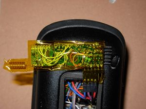
[[File:Wch2-lora-v1.jpg|thumb|A lora-promini module, encased in Kapton tape for insulation. ]] | |||
I originally used nrf24l01 modules for the radio communications between robot and remote control. These don't have the best range, and after reading about the impressive range from LoRa radio modules, I decided I would try these instead. Since I might want to experiment with different radios in the future, I decided I would also make the radios into an independent module, which operate the radio separately from the h-bridge and remote control microcontrollers. That way, I could also avoid any nonsense with different radios requiring different pins, different power supplies, and different signal voltages. | |||
===Aug 2019 version=== | |||
I took an 3.3v Arduino Pro mini and attached a RFM95 Lora module. I used the RadioHead library for controlling the radio. Finally, I added a logic level converter which provides the Arduino I2C pins and the UART pins, either of which could also be used for general purpose IO, and interface the whole module to a 5v system or whatever. | |||
To make a long story short, the radio modules appear as I2C slave devices. Taking after the RadioHead radio library examples, there are 2 versions of the module programming, a server module which rides on the robot, and a client module which the remote controls use. | |||
Starting on the client side, you write 30 bytes to I2C address 8. The module then transmits the 30 bytes to the server module, which then responds with 30 bytes of its own. The CRC of the response is checked to see if we got a valid message. If there is a valid message, it copies the valid message into a buffer. At any point in time, you can read 31 bytes from address 8, the first byte of which is value 1 if a new valid message has been received, and the other 30 bytes are the 30 bytes of the message. | |||
The server side is almost the same, but there is another buffer for transmitting, because the server will only transmit when a valid client message is sent. Also on the server side, I have used an additional signal wire that signals when a valid message comes in, so that the h-bridge microcontroller only needs to monitor this wire instead of reading I2C data all the time. | |||
Again, not perfect, and not the most efficient, but again, does work. The size of 30 bytes was chosen because the size the Arduino I2C commands can work with at a time is apparently 32 bytes. Of note is that the server/client architecture is probably not needed within the modules themselves; it would probably be preferred that I add some extra flag wires and let the remote control and h-bridge controller handle it themselves. This would make both radio modules identical, and get rid of a little bit of delay - as it stands now, the server radio module sends out its transmit buffer immediately instead of waiting for new, current data to be copied in. | |||
Files are at the end of this article. | |||
Relevant files are rf95-client-i2c and rf95-server-i2c, which are the actual sketches loaded on the LoRa radio modules. | |||
===Version 2=== | |||
Not long after the initial version, I decided to slightly alter the setup. This is now listed on its own project page [[gLora module]]. | |||
Now, both remote control and h-bridge board use the same radio module, and handle the client/server architecture on their own time. Each device is informed when a new message comes in, and can transmit out messages. Buffer size is now increased to 32 bytes. | |||
==5 - Remote Control== | |||
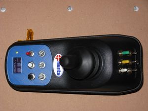
[[File:Wch2-remote-control.jpg|thumb|The remote control unit of the system, made from the old hand control of the wheelchair, because I wanted to reuse the original joystick.]] | |||
The entirety of the original controller was contained inside the joystick handle. The original joystick is a quite good one, so I decided to gut the unusable electronics and reuse the case. There's plenty of space inside to fit lots of switches, a battery, and microcontroller. The only issue is that the base of this case is aluminum, so I had to place the radio module on the outside (for now). | |||
The design of the remote control is really pretty simple. Switches and buttons are hooked up to digital inputs on an Arduino Pro mini, and potentiometers and the joystick are attached to the analog inputs. An 18650 battery and boost converter provides 5 volts to the system. The tiny OLED screen is an I2C device, as is the LoRa radio module I made. | |||
In software, I smooth the joystick inputs, and compute what the target speeds of the left and right wheels are given the position of the joystick. This gets sent out over the radio, and the h-bridge box returns with some telemetry information, which gets displayed on the screen. | |||
It's not perfect, but does work. The main limitation is the speed at which I can draw things on the screen, so the radio messages get sent out a little less often than I would like. This can probably be optimized, but I'll leave that for the future. | |||
==Files== | |||
None of the below files are organized well for a "release", but they are here anyways for your own research purposes. | |||
Eagle files for this H-bridge board can be found here: [[File:Wchmotor2-eagle.zip]] | |||
A dump of my Arduino sketch folder contains all the revisions for my radio modules, and the sketches running on the robot and remote control. Be careful, earlier versions sometimes use different hardware! - [[File:Wch2-arduino-v3.zip]] | |||
Latest revision as of 11:08, 8 August 2019
After my attempts to modify the settings of the existing wheelchair controller I accidentally erased all the board settings and was left with an inoperable board. Since it is almost impossible to locate the correct file for my particular controller, I decided to construct a new motor controller. This would give me the added advantage of full control over each wheel motor, and I could write all my own control algorithms (though these do not necessarily come easily). I eventually extended this to support rotary encoders on each wheel, a custom radio control setup, and a robotic arm, turning an old electric wheelchair into a powerful general robot platform.
This project is ongoing, and as it stands today, was completed over a series of many months, and I didn't document most of it at the time. The following is, in general, the process I went through to develop this system.
1 - DC motor controller (H-bridge)
Like the original wheelchair, I needed to operate two 24V DC motors. I was not sure of the amperage, but I know that the batteries have an inline fuse for 12A, and that the original controller operates with just 4 single TO-220 mosfets on each motor (part numbers indicated rated for 30A). I couldn't test the motors under load very easily without a controller, so I estimated that a motor controller of 20-30A would do the job.
The style of motor controller, in both the original wheelchair controller and my replacement is known as an H-bridge. In simple terms, it is a circuit using four switches, which allow you to connect and disconnect either terminal of a DC motor to either + or - of a battery. In this way, you can make the motor run in either direction, and even control the speed by turning on and off the switches really fast.
I bought a cheap Chinese h-bridge board but it failed almost instantly, so for my next attempt I decided to roll my own. I based my design on the open source Robot Power OSMC, with some changes. Firstly, I reduced the number of power mosfets by 1/4, since the original OSMC is rated for 160A, and I didn't need anywhere near that much power. So, instead of 4 mosfets on each branch, there is just one. The rest of the controller remains the same, which mostly consists of the HIP4081A mosfet controller. Next, I doubled up the controller, adding a second channel so I could drive a second motor. The last step was designing a PCB, which was straightforward except for the traces which would carry the high motor current. Since I wanted to use a cheap PCB service with correspondingly thin traces, I left off the solder mask on those parts (exposing the bare trace), and then filling the entire trace with excess solder, which has proved to work fine.
The resulting board works fine, although there could be some improvements to improve the board layout (this is only the second board I have designed, ever). Additionally, the board lacks seperation for the logic power and motor power, forcing me to add it in later when I realized I still needed the board powered even when I wasn't using the motors.
2 - DC motor controller (Supporting components and processor)
More than 2 H-bridges are needed to operate the wheelchair. Each motor has an electromagnetic brake, so to be able to run the motors you must first apply power to the brake which will disengage it. I solved this by using a relay to apply power to the brakes. In addition, the same relay allows power to flow into the H-bridge. Therefore, no power can get to the motors with the brake on. This also serves as a safety feature of sorts, de-energizing high power parts of the circuit when they are not being used. Another, smaller mosfet allows a microcontroller to switch the relay.
For the microcontroller, I used an ATMEGA1284P with the Mightycore arduino compatible firmware. This particular chip has plenty of IO pins, and enough PWM pins that aren't also using timers used by other functions of the chip. This makes it much easier to, say, change the PWM frequency and see how the motors perform, maybe even eliminating the PWM noise the motors make (though I haven't tried that yet). Basic functions of the microcontroller are:
- turns on the relay (disables brakes and applies power) when motion is requested, and turns it off after a timeout when no motion is requested
- provides PWM signals to the H-bridge (allows control of power to the motor from 0 to 100%)
- calculates on the control algorithm (in first version, just a feedforward that adjusts power to each motor, in second version, this plus a PID controller that acts on measured motor speed)
- derives wheel speed using two quadrature encoders
- manages nrf24l01 radio for communication to remote control
All that is left is a handful of power supplies to operate the radio and microcontroller, and some programming.
3 - Quadrature encoders
The original version of this homemade controller just controlled the power to each wheel, but after I took a controls class in college, I thought it might be interesting to experiment with some closed loop controllers. This meant I would need feedback of the motors speed and/or position. I decided to make 3D printed encoders, and attach them to the ends of the motors, before the gearbox. These aren't the highest precision or most accurate, but they were easy and cheap to make.
First, I hooked up two pairs of IR leds and matching photodiodes. Then, I designed a rotor and housing to attach to the motor axle and the back housing of the motor. One interesting thing I learned when making these is that the ABS plastic I was using is somewhat transparent to IR light, but the parts were thick enough for this to not matter so much. The pairs of sensors are placed 90 degrees out of phase of each other, ie, when one sensor is in the center of a rotor vane, the other is at the edge of the rotor vane. When the rotor rotates and we observe the signals coming off of the sensors, we can figure out the direction and speed of the motor. Imagine drumming your fingers on a table; you can easily tell if the motion is left to right or right to left, as well as how fast you are doing it - this is the mechanical/electrical equivalent. Two digital signals are sent to Atmega interrupt pins (pin change interrupts, which there are a lot of), for processing as a quadrature encoder. By observing which signal changes first, we can figure out what direction the motor is turning, and by counting changes and dividing by time, we can calculate speed.
4 - LoRa radio modules
I originally used nrf24l01 modules for the radio communications between robot and remote control. These don't have the best range, and after reading about the impressive range from LoRa radio modules, I decided I would try these instead. Since I might want to experiment with different radios in the future, I decided I would also make the radios into an independent module, which operate the radio separately from the h-bridge and remote control microcontrollers. That way, I could also avoid any nonsense with different radios requiring different pins, different power supplies, and different signal voltages.
Aug 2019 version
I took an 3.3v Arduino Pro mini and attached a RFM95 Lora module. I used the RadioHead library for controlling the radio. Finally, I added a logic level converter which provides the Arduino I2C pins and the UART pins, either of which could also be used for general purpose IO, and interface the whole module to a 5v system or whatever.
To make a long story short, the radio modules appear as I2C slave devices. Taking after the RadioHead radio library examples, there are 2 versions of the module programming, a server module which rides on the robot, and a client module which the remote controls use.
Starting on the client side, you write 30 bytes to I2C address 8. The module then transmits the 30 bytes to the server module, which then responds with 30 bytes of its own. The CRC of the response is checked to see if we got a valid message. If there is a valid message, it copies the valid message into a buffer. At any point in time, you can read 31 bytes from address 8, the first byte of which is value 1 if a new valid message has been received, and the other 30 bytes are the 30 bytes of the message.
The server side is almost the same, but there is another buffer for transmitting, because the server will only transmit when a valid client message is sent. Also on the server side, I have used an additional signal wire that signals when a valid message comes in, so that the h-bridge microcontroller only needs to monitor this wire instead of reading I2C data all the time.
Again, not perfect, and not the most efficient, but again, does work. The size of 30 bytes was chosen because the size the Arduino I2C commands can work with at a time is apparently 32 bytes. Of note is that the server/client architecture is probably not needed within the modules themselves; it would probably be preferred that I add some extra flag wires and let the remote control and h-bridge controller handle it themselves. This would make both radio modules identical, and get rid of a little bit of delay - as it stands now, the server radio module sends out its transmit buffer immediately instead of waiting for new, current data to be copied in.
Files are at the end of this article. Relevant files are rf95-client-i2c and rf95-server-i2c, which are the actual sketches loaded on the LoRa radio modules.
Version 2
Not long after the initial version, I decided to slightly alter the setup. This is now listed on its own project page gLora module.
Now, both remote control and h-bridge board use the same radio module, and handle the client/server architecture on their own time. Each device is informed when a new message comes in, and can transmit out messages. Buffer size is now increased to 32 bytes.
5 - Remote Control
The entirety of the original controller was contained inside the joystick handle. The original joystick is a quite good one, so I decided to gut the unusable electronics and reuse the case. There's plenty of space inside to fit lots of switches, a battery, and microcontroller. The only issue is that the base of this case is aluminum, so I had to place the radio module on the outside (for now).
The design of the remote control is really pretty simple. Switches and buttons are hooked up to digital inputs on an Arduino Pro mini, and potentiometers and the joystick are attached to the analog inputs. An 18650 battery and boost converter provides 5 volts to the system. The tiny OLED screen is an I2C device, as is the LoRa radio module I made. In software, I smooth the joystick inputs, and compute what the target speeds of the left and right wheels are given the position of the joystick. This gets sent out over the radio, and the h-bridge box returns with some telemetry information, which gets displayed on the screen.
It's not perfect, but does work. The main limitation is the speed at which I can draw things on the screen, so the radio messages get sent out a little less often than I would like. This can probably be optimized, but I'll leave that for the future.
Files
None of the below files are organized well for a "release", but they are here anyways for your own research purposes.
Eagle files for this H-bridge board can be found here: File:Wchmotor2-eagle.zip
A dump of my Arduino sketch folder contains all the revisions for my radio modules, and the sketches running on the robot and remote control. Be careful, earlier versions sometimes use different hardware! - File:Wch2-arduino-v3.zip
