2024-02-10 | [retrocomputing] [sinclair]
The Timex 1000 (aka Sinclair ZX-81) is probably best known for one thing: being made as cheap as possible. You get 2K of RAM, a terrible membrane keyboard, and there isn't even a power button.
The only video output (with no sound) is NTSC, but it's put through an RF modulator for use with a standard TV, which would have been common in the day. After I did my video mod for the TRS-80 color computer, I realized that I actually have just one useable TV with a working tuner - most of my CRTs are either tiny portable versions (with resolutions too small for computer text) or monochrome monitors which never had a tuner in the first place.
So it makes sense to add a composite video output to this. One method is to simply add an emitter follower circuit, much like the simpler CoCo mods. But, I'm aware of another circuit called the ZX8-CCB. I can't verify that the video output is any better or worse than a simpler circuit, but it does have one killer feature: you can invert the video signal so it's white-on-black instead of the standard black-on-white. Black-on-white is certainly more common these days, but it seems rather antithetical to the use case of the green or amber computer monitor crts.

Here is the schematic for the ZX8-CCB circuit, as included with the original instructions. Unsurprisingly, the video invert feature is done by sending the signal through an XOR gate. The rest of the circuit is responsible for essentially breaking apart the original signal and putting it back together at the proper signal levels. It is also designed to add the "back porch" section of the waveform for those machines using the older ULA 2C184E, but mine has the newer ULA 2C210E which has had the back porch the whole time (this is a well known thing - google "sinclair ULA back porch" for more details).
The whole thing is assembled on a tiny PCB with some of those individual gate chips in the SMD (SOT-6?) package. I'm usually one to make my own version of stuff, but this is an already solved problem which would cost me more to make myself, so I picked up a premade board.
I sort of wanted to keep the rf modulator connected, but the video invert feature can be controlled by a switch, and the only switch available without cutting the case is the channel select. I'll have to be satisfied with losing that feature.

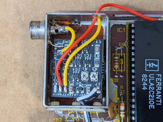
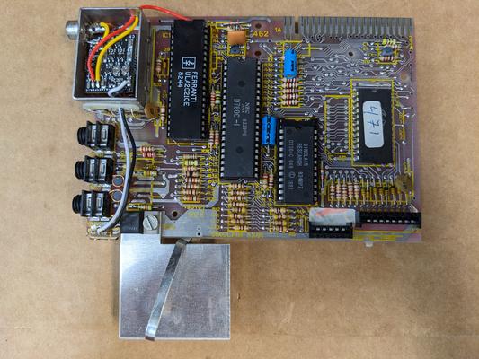
Firstly, the board installs nicely into the RF modulator box. The original RCA jack is reused for the composite video, you just unsolder one capacitor and an LR filter. The only other modifications needed are to drill a couple holes in the box so the wires can enter. Note that I chose not to dispose of the RF modulator guts - the new board is simply hot glued on top of them. So, the original parts are still there and could be reversed if needed. I also desoldered the 3 input leads on the RF modulator (which are (assuming) +5V, channel select, and the video input). The new board needs only power, gnd, and the video signal (from ULA pin 16) to work.

The inverse video mod is done by shorting J7 on the board. I tied this into the channel select switch, but I first isolated the switch by cutting the traces going to it. All the J7 jumper does is control whether a high or low signal is going into the XOR gate, and the original switch does just connect the middle pin between GND and +5V, but on the new board the XOR input has a pullup tied to a filtered version of V+, and I figured I wouldn't introduce extra noise in there. I did not try to see what happened without the traces cut - it might very well work anyways, but in any case the cuts are small and easily reversed.
The last part was the adjustment, which is 2 potentiometers. One (R1) controls the threshold for the sync portion of the video waveform, and the other (R2) controls the threshold for the image portion. This was probably the most difficult thing to set up - both adjustments have a very wide range, and the Sinclair generates one of those signals which is merely "composite like" rather than a properly formatted NTSC signal like I wanted to achieve on my CoCo. So you can look at the scope, but still not really be able to tell if what you're looking at is correct.
I brought out a composite monitor, which did not help with the adjustment, as it could, with its auto gain, pick up even a completely incorrect video signal and make it look like it was working, and until I corrected my brightness and contrast I did not realize that I was working in the completely wrong section of each potentiometer. When adjusted correctly, you should be able to flip the invert switch and the picture should immediately swap colors.

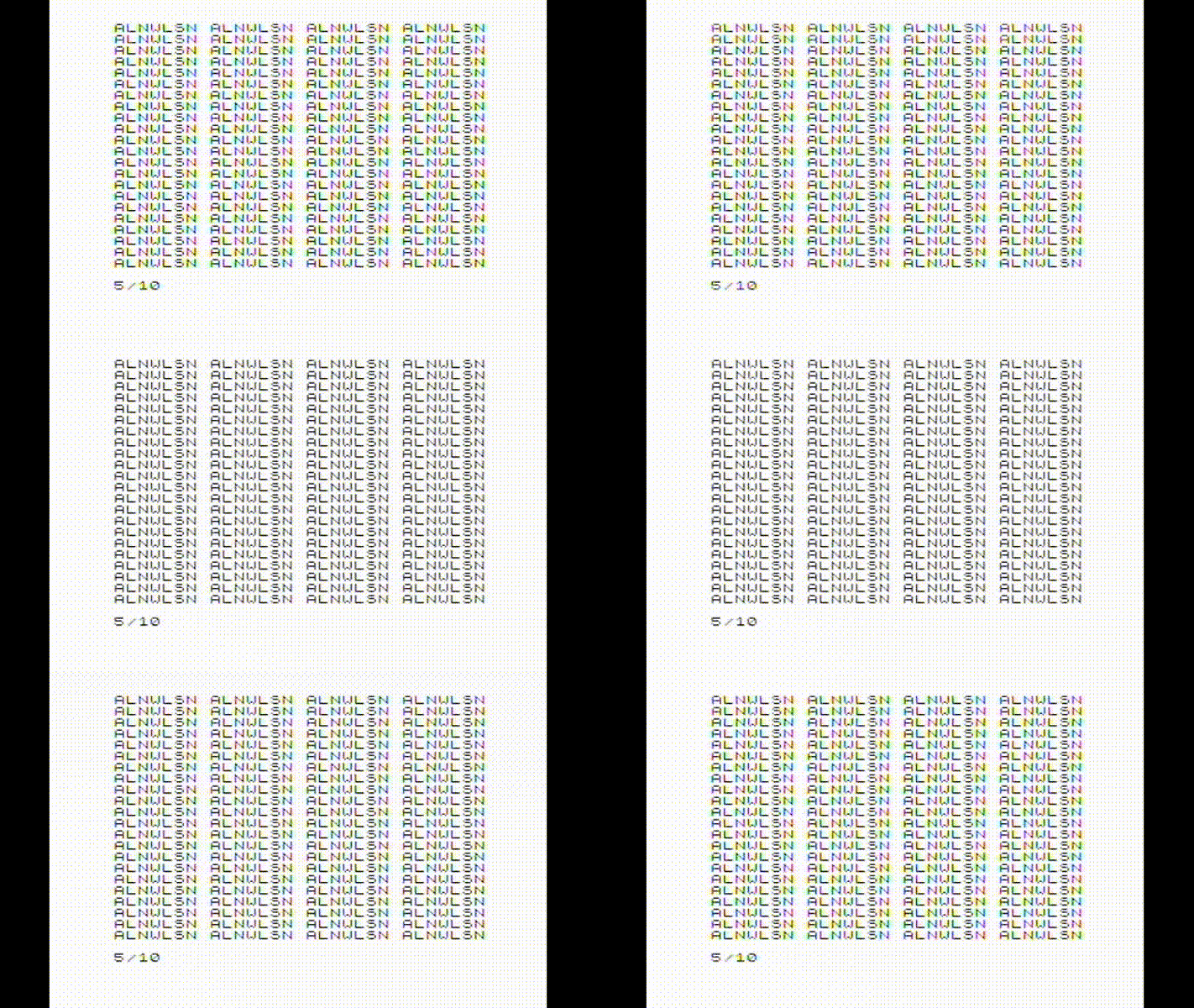
Here is what the final product and the video looks like, including switching between the normal and inverse video modes. The color banding on the letters is probably from the capture card trying to interpret ntsc color where there isn't any - this can be fixed by turning the saturation on the capture side all the way down.
