2024-01-17 | [retrocomputing] [coco] [trs80]
I bought a Model 4 recently, and when I went to pick it up, the seller offered me a Color Computer 1, which I brought back with me. The CoCo series is a a completely different architecture than the Z80 system of the Model I/III/4, and was sold as the 'lower cost' home computer (despite having an arguably better 6809 processor). There seems to be a lot of interesting things to explore down this path, but first I have to get my machine working so I can use it.

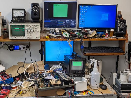
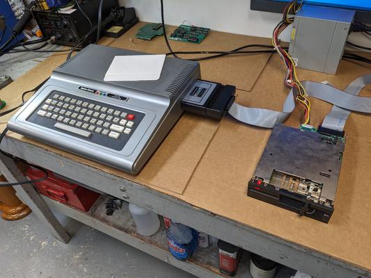
When your bench looks like this, you know you're having a good time
I got pretty lucky; my Coco1 is a Rev F board (marked 8709285 on the PCB), and upgrading from the stock 16K of ram to 64K is easy. Simply remove the RF shield over the dram chips, move 3 jumpers under there from the 16K to 64K position, install a 4th jumper near the MC6821P IC, and remove capacitors [C58, C60, C62, C64, C66, C68, C70, C72]. Like the model 12/16/6000, the caps are on a power pin for the 4116 DRAMs but it's an address pin for the 4164, so those decoupling capacitors need to be clipped out or the address won't make it in.
Then, you just pull out the 8x 4116 chips and replace them with 4164 DRAMs. A bunch of the 4164 chips I had on hand were bad, and I ended up borrowing a known good set from another machine, before swapping in the 'unknown' chips in my stock one-by-one until all 8 were replaced.
Apparently, the COLOR BASIC 1.1 that is in ROM is new enough to work with 64K, but earlier versions might not be. It still only shows less than 32K free when I run the ?MEM command, so I don't know.
I didn't take any pictures here, but this is a well documented process; here's a video.
The Coco has just RF only for video output - that's the kind where you connect the RCA connector to the antenna socket of your TV and tune in to channel 3 or 4. This is not too useful for me because the only color TVs I have that still have an analog tuner in them are old tiny portable units with dim and low resolution CRTs. The one slightly larger color set I had seems to have a broken tuner, so that's going nowhere too.
There are various mods that you can use to get video out to something else. If you're going for overkill, there is the excellent CoCoVGA which goes under the video generator chip and listens to the signals with an FPGA. There is at least one S-Video mod, but it requires removal of the RF modulator, which I wanted to keep for historical accuracy. That narrows it down to Composite (or CVBS/RS-170A/NTSC/analog/whatever the correct standard name is), and a small pile of mods to do that. I tried this one and some others, but was underwhelmed. It's probably a good time to take a step back and see how we can do things correctly.
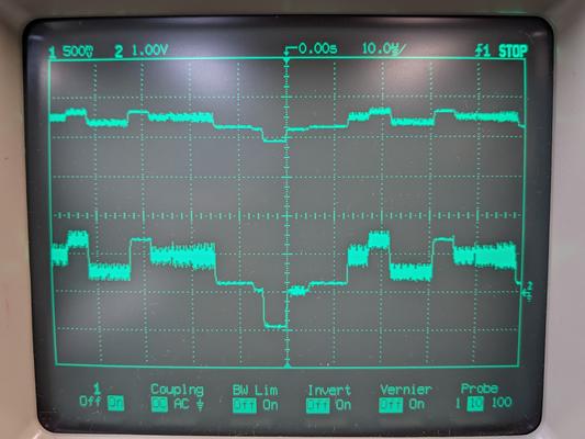
On the scope, a single line of video looks like this, which I'm sure you've seen before:
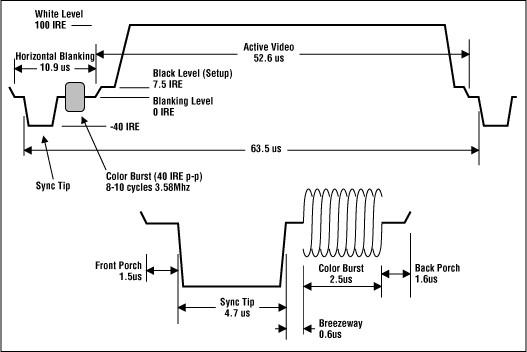
Note the IRE units - one IRE is 0.007143 volts. So the video signal goes from about 0 to 0.75V, and the sync pulse is negative.
Another part about composite video is that it is supposed to be 75 ohm terminated. If you get a multimeter and measure the input of some video device, you should find a resistance of about 75 ohms. So you can't exactly put a composite signal in wherever you want; it should be able to drive the signal. (Though to be fair, lots of sets have auto gain control, AC coupling, etc. that make all sorts of signals "work" even if they aren't in spec.)
On the CoCo, the best place to get the video signal is probably pin 12 of the MC1372. This chip is actually supposed to be an RF modulator, but the CoCo uses a separate RF modulator unit (Astec UM1285-8), so it is used to only generate the video instead (which is one of the specified uses, see p.12 of the datasheet).
If I measure the signal of pin 12, I get something that looks like composite video, but it's got a DC offset of about +4 volts. Also, it's about half the amplitude we want. If I was any good with analog electronics, I'd probably be able to come up with something simple, but I went with a video op-amp instead.
What I ended up building was this:
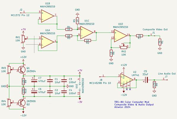
The MAX4395ESD comes in a SOIC-14 package with 4 op-amps inside. Two are used to buffer inputs, the middle one is a subtractor (to subtract the DC offset away), and the last one is an amplifier/driver. Note that R1 is actually inside the monitor you connect to, it's not part of the circuit you build. Since the input is very high impedance, it does not affect the RF modulator and you can still use it if you want.
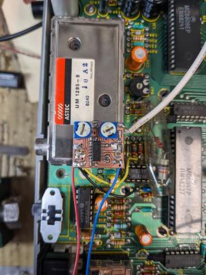
The video op amp board. The yellow wire is the video signal input off pin 12 of the MC1372.
The power supply is a bit of an afterthought. I originally wanted to power the video op amp from -/+ 5V which the coco has inside already, but I found that driving it with 5V it did not have enough juice to reach high enough to buffer the ~+4.5V signal off pin 12. You do need negative voltage too, because the sync pulse is meant to be negative volts. Unfortunately, I can't just switch the power supply to +/- 12V, which is also present on the coco board, because the maximum voltage difference the MAX4395 can be powered with is only 10V. Oops. But, I powered it with some batteries and found that +7V was enough on the positive side to buffer the input, and that leaves -3V on the negative side, which also works.
So now I have to get +7 and -3V power sources from somewhere, but I didn't happen to have any negative voltage linear regulators on hand. However, a series linear regulator can be made from a BJT transistor, a couple resistors, and a zener diode. I didn't have any zener diodes on hand either. But, what a series regulator really is a emitter follower. If the input to my DIY linear regulator is itself already regulated, you can use a voltage divider in place of the zener diode, and get a regulated voltage which is lower (or higher for a negative voltage) than its input. Replace the voltage divider with a potentiometer, and you have something you can easily adjust to get the right voltage.
So, this is what I did. I built the +7 supply around the LM7812 already present on the coco.
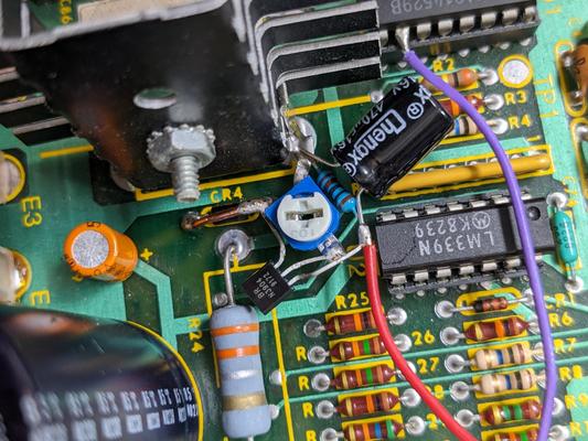
The -3V supply, with a PNP transistor, is built around the -12V LM7912 regulator:
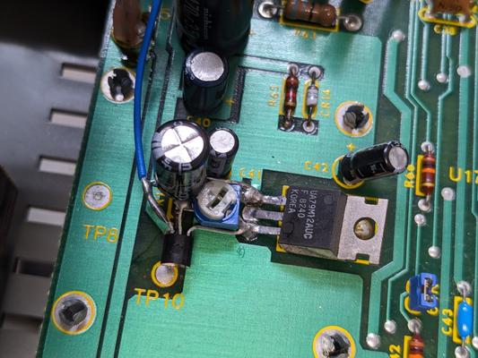
Powering this for the first time, I found that the transistors do get pretty hot. This is not unexpected for a linear regulator, but maybe I underestimated the amount of heat. The negative supply is hit hardest, since it has more volta to burn off. Lets see, I measured the current going to the op amp at about 30mA. The voltage drops by 9 volts, so that comes out as a bit over a quarter watt. No wonder the transistor is getting so hot!
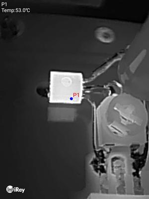
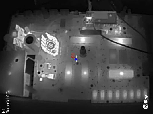
At 50C, the transistor is firmly in the "too hot to touch" category. But, the 2n3906 is supposed to be good for +150C. However, it's rated for 1/4 watt at 60C, which is pretty close to what we're at now, so it's really probably on the edge of being in spec. Perhaps I should swap out the transistors for proper TO-220 packaged linear regulators like the LM317 / LM337.
But, the transistors don't really run much hotter than the other components on the board. Also important is that the -/+ 12 regulators still stay cool to the touch, so it looks like the existing power supply is up to the task of powering my mod.
On the scope, you can see the change in signal. The input (top signal) is the raw video signal from pin 12, and the bottom signal is a properly offseted and gained composite video signal which drives a properly terminated 75 ohm video input.
All this and I haven't even shown how it looks.
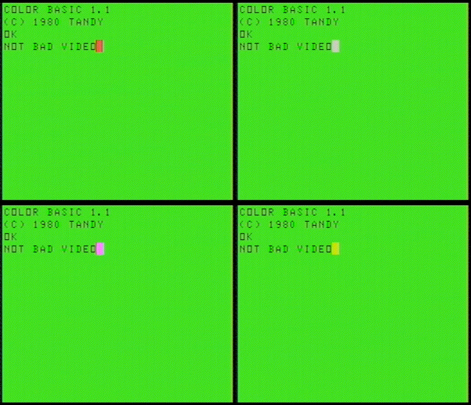
Not Bad! This is a real video capture as done through the old PCI capture cardI have in the shop PC. It looks better on a proper composite color monitor.
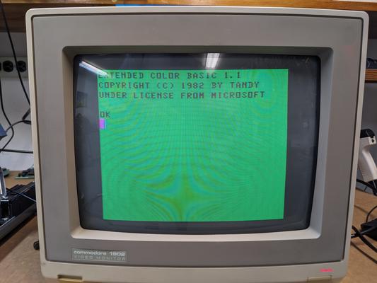
For audio, the RF modulator gets it's signal from pin 10 of the MC14529B, an analog switch IC. As measured from this point, it comes out at about 1V peak to peak, about right for a line output, but at a +2V DC offset. It's easy to just add a RC high pass filter to remove the offset, but the audio actually comes from a resistor DAC of fairly high resistances. Since the analog switch IC doesn't do any buffering and is bi-directional, applying a high pass filter here effectively shorts the audio signal to GND. I noticed a LM741 op amp on board, and decided it would be easy to solder another one on top, using the lower one's power supply, and set up a voltage follower to buffer the audio, which goes through a high pass filter afterwards to remove the DC offset. This worked very well, and now I can have audio output in addition to video.
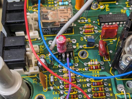
Stacked op-amp audio buffer and RC high pass filter.
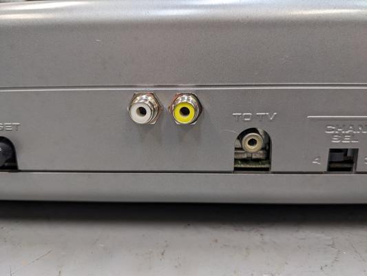
There is nowhere in the case to put connectors for the audio and video I just added, so holes need to be drilled. I use a couple of these RCA jacks I had on hand, which can be soldered first and then installed from the inside, which is the opposite order of most RCA jacks. Switchcraft BPJR03X or DigiKey SC1991-ND are similar ones. Both of mine were white, but that is easily fixed with a yellow marker.
When installed in this location, they just clear the RF modulator box.
For the next step, I went and bought the disk controller cartridge. Mine is a 26-3029 which was for the CoCo 2 but works just fine on the Coco 1. It didn't come with any disk drives, but I have plenty of those around, and the controller uses ordinary PC disk drives, with a straight (Shugart) 34-pin cable with card-edge ends.
Insert the cartridge, turn it on, and nothing happens. If it worked, we should see "DISK EXTENDED BASIC" on the screen, but it still says "COLOR BASIC 1.1".
What we need is the Extended Basic ROM, which is installed in the empty socket next to the normal Color Basic rom. It's an 8K ROM who's image can be found here (I used the 1.1 version), but it has a different pinout than a normal 2764 EPROM.
The 2764 is 28 pins, and needs to go into the socket for a 24-pin 2364 ROM (or MCM68766 EPROM). This is a somewhat common problem, and you can get or make an adapter. The difference is just that there is an extra enable pin, a few pins to tie to VCC, and a couple address pins that have moved locations.
For my part, I just made an adapter on perf board. Sometimes, it's nice to just have things in hand quickly.
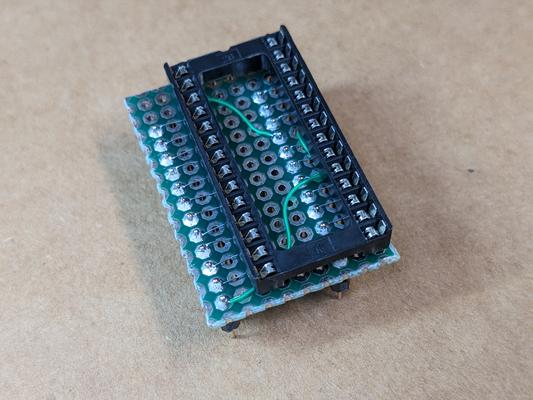
That fits into the socket like this. Pro tip, when you want thinner header pins that fit into a chip socket properly, what you want are called "swiss" machined pin headers.
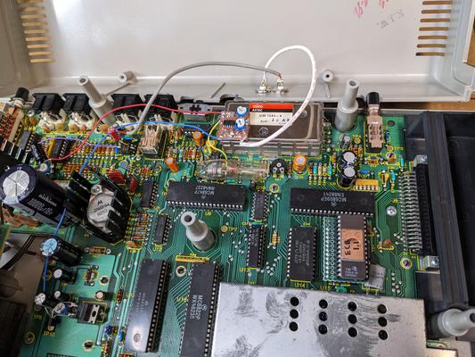
And then the screen looks like this:
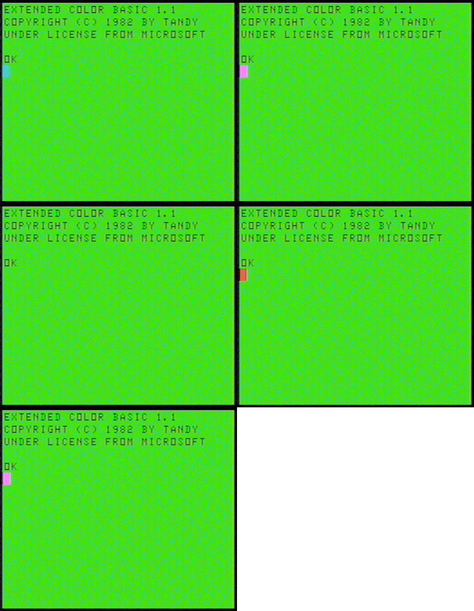
So all that is left is to hook up a drive, put a disk in, and install the cartridge.
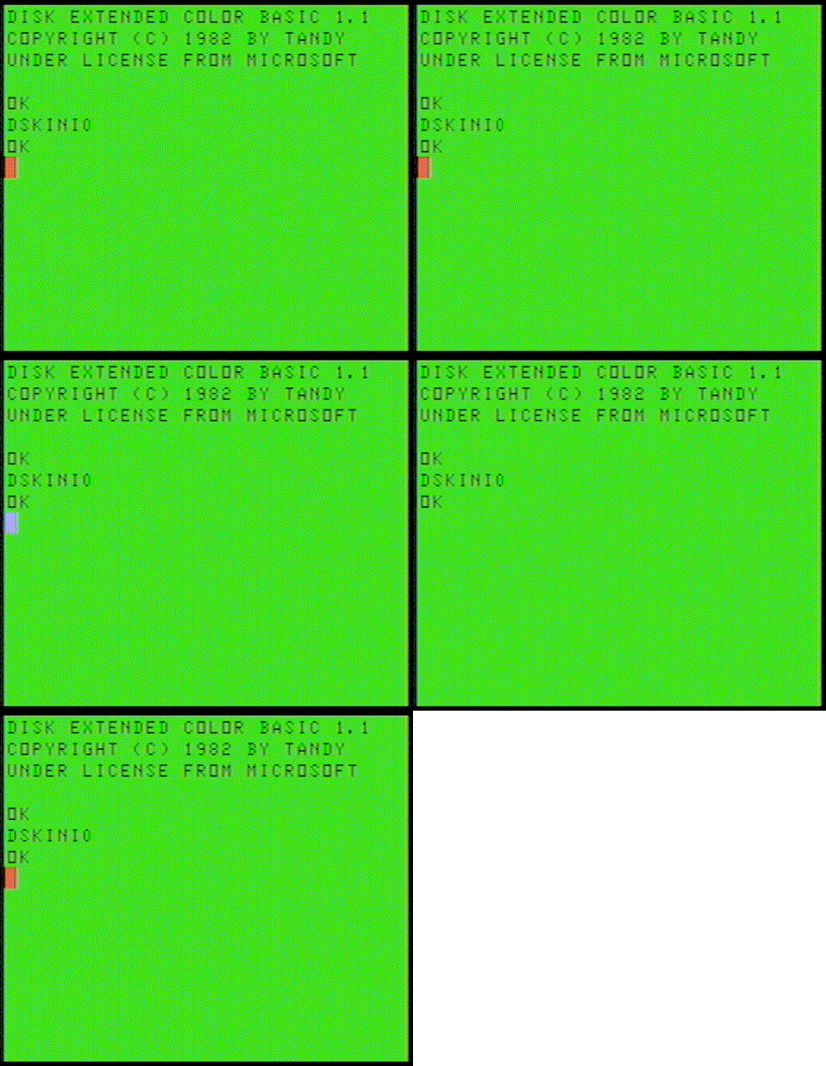
It worked! I was able to successfully format a disk with the DSKINI0 command.
All for now.